project13:Styling
Contents |
Introduction
In the 'interaction' section you have noticed a rough draft of the program for the Knowledge Centre. In this part of the website, the final design is presented in 4 steps. Firstly, the concept and references are illustrated. Secondly, a short animation will show all of the components of which the building consists. Part of the styling are the plan drawings. These will show where certain program is located and how the routing is arranged. Also, some connections brought up in the 'interaction' section will be shaped and visible. This is followed by some images to present the atmosphere in the building. The section is concluded by a short summary on how the project is created with grasshopper and rhino.
Concept and References
The project
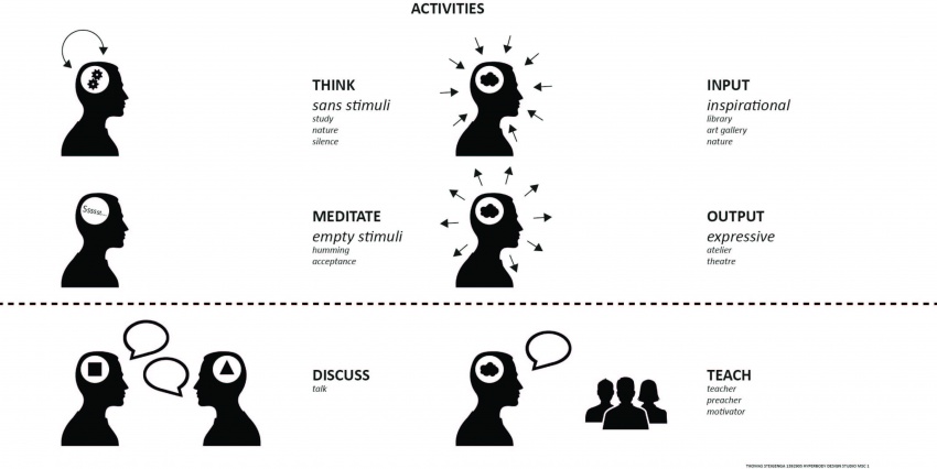
The most important aspects of the Knowledge Campus are learning, talking and thinking. Learning is generally done at one of the other projects on the campus. Talking and thinking are things that happen in the Knowledge Centre.
The Knowledge Centre should be designed in a way that it stimulates these activities. That means, a building, with lots of different spaces with different characteristics, different levels of publicness, different heights and different spatial experiences.
The program and concept
The two most important aspects of the program definition are the hotel studios and the assembly hall, as the latter will have a huge representational impact on guests and other visitors.
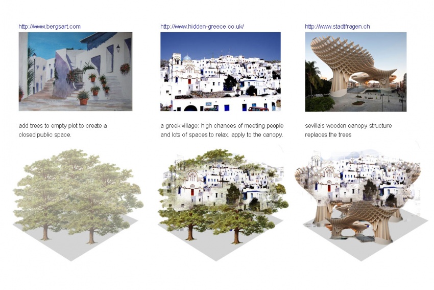
Two references illustrate quite well the points made above. Both references direct us towards southern Europe. The first is in Greece. Mentioning 'Greek village' will raise almost the same image in everyone's mind. A diverse village, consisting of slightly winding street but yet orthogonal white buildings. The buildings are characterized by blue window frames and doors. Plants grow everywhere and the village feels like a home. Usually a village of this sort is built on a hill. This results in many height differences and steep alleys and streets. It creates beautifully surprising see-throughs and interesting housing configurations. Many different, hidden, more private and exposed, more public, places and streets. A strong image. This image also reflects lots of people on the streets. Sitting, relaxing, talking, walking, etc. People in front of their doorstep, old men playing chess and kids enjoying the weather. Generally: people meeting each other. And that is exactly what is project is looking for.
The second reference is a modern icon. Built by Jurgen H. Mayer in Sevilla, the Metropol Parasol winds up the minds of many architects, architecture students and ordinary citizens from all over the world. The parasol creates a fantastic public space which is experienced differently from many different angles. This construction already supplied lots of different activities organized by the government, private parties but most of all, by the public itself. This magic of this structure will be the inspiration for the assembly/auditorium hall.
Together these two references create this project.
How is the building assembled?
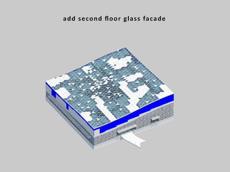
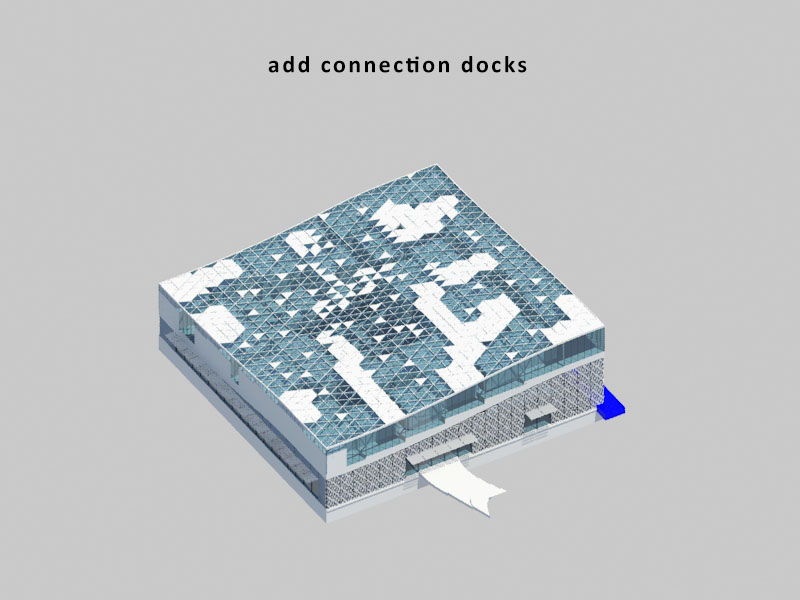
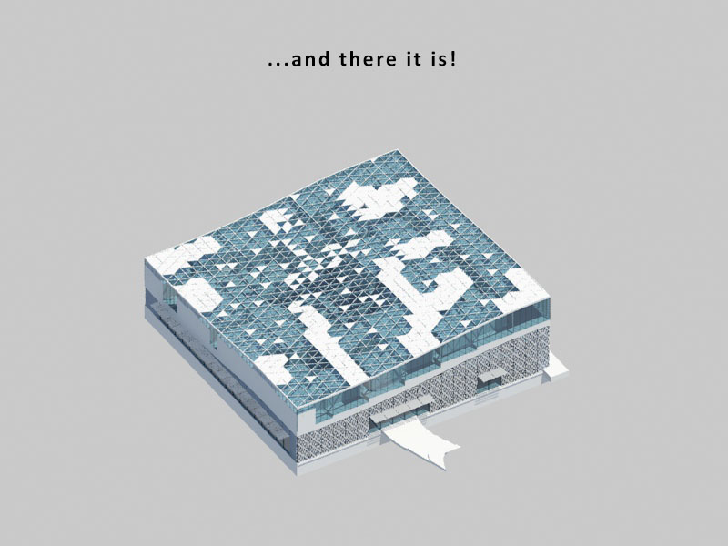
Now we are of to the second part, the introduction of the actual building. In the animation viewed beneath this text, you can see of all the elements this project consists of. In short:
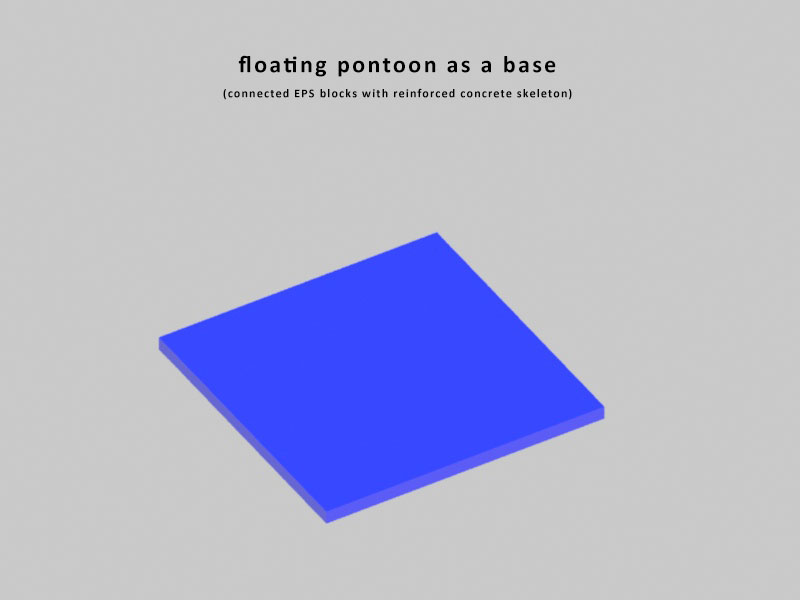
- -Buoyancy is created by an EPS and reinforced concrete pontoon;
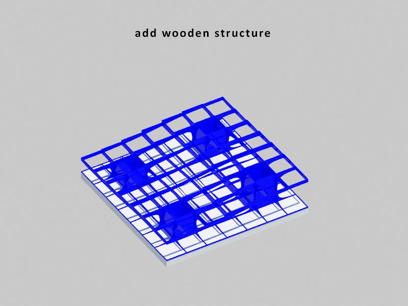
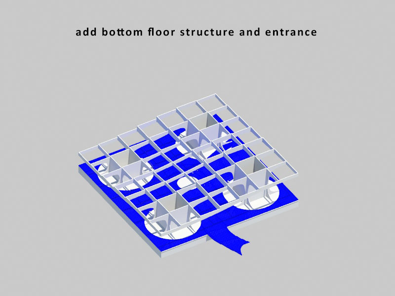
- -On this pontoon, the Parasol structure, creating a roof and space for the auditorium and a hillside for the Greek village. Around the stems of the structure the functions who are need of a clearly defined space are grouped, for instance the vertical routing, administration and service area;
- -The floor interacts in form language with the next door project of De Geleerde Netwerk. The wooden path of the urban plan of that project flows without any bumps directly into the auditorium hall of the Knowledge Centre;
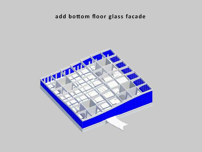
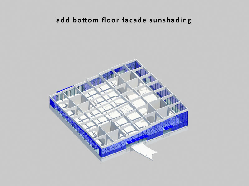
- -The auditorium is wrapped in a transparent envelope with timber horizontal sunshading, also referencing to form language of DGN (De Geleerde Netwerk);
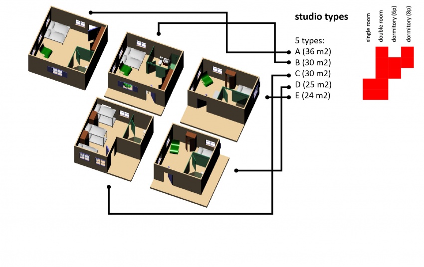
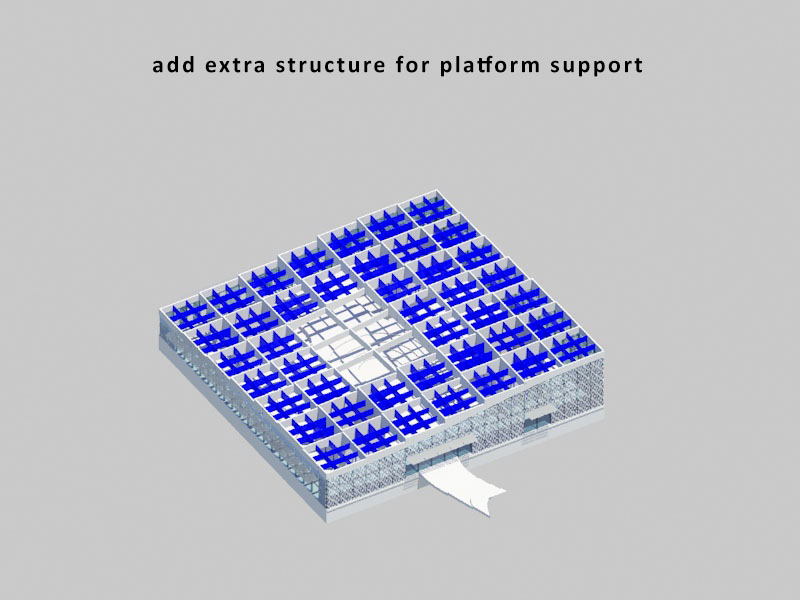
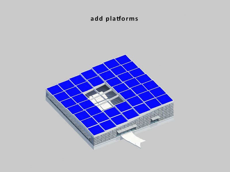
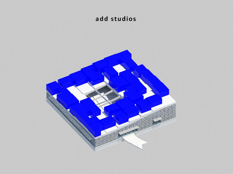
- -After, the Greek village is created. Platforms create the landscape with different elevations, on this, five different studios can be placed. The random placement of these studios, taking in account the access, creates the wonderful differentiation of places one can find in a Greek village. The different studios have different amounts of square meters and therefore have different functions: single rooms, double rooms and dormitories.
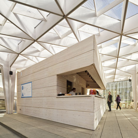
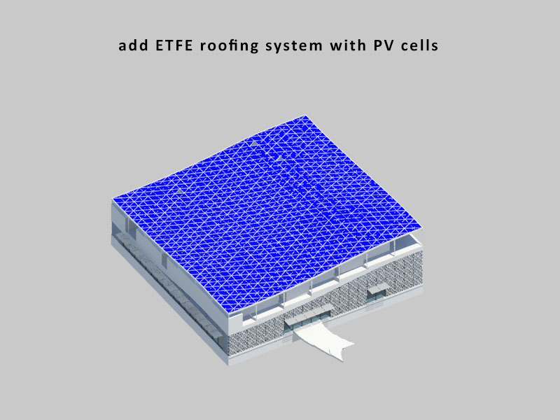
- -Because the climate in Rotterdam is not quite the same as the climate from the reference in Greece, one can imagine that if the public area between the studios on the roof has to be used for more than a couple of months per year... it has to be closed of from the elements. That is why, the Greek village is roofed with a reference from the Northern Europe. It somehow is the little tiny cousin of the Metropol Parasol. It is the World Design Capital Helsinki 2012 Aalto University wood studio (image from Dezeen).
To illustrate all of this, an animation:
How does the building function?
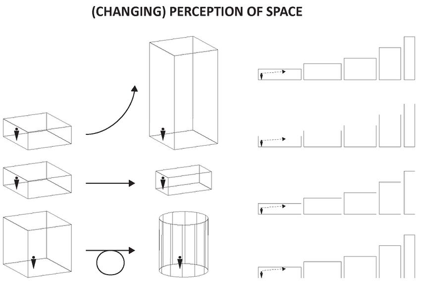
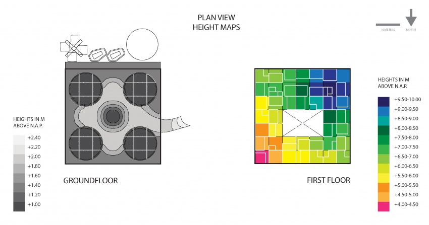
In this paragraph some different plans are displayed, showing different aspects of the building. The first one shows the height difference of both floors. The bottom floors height differences reflect the character of DGN's urban plan. The height difference in the bottom of the Greek village, the first floor, have been covered above.
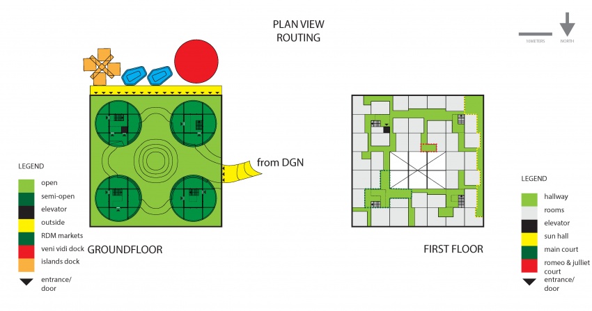
These plans show the routing. One can enter the building via two ways. One is physical and fixed directed towards the west, via a connection/bridge to DGN. This will be the main entrance. A secondary acces is available towards the south of the project. A floating dock is placed for the full width of the building (the project measures 42x42m). Besides people being to relax and eat on this dock in the sun, different water vehicles can connect to it. RDM's floating market can provide food (which is not available at the Knowledge Centre itself - everyday there will be a floating market delivering the food). The Islands will provide transport towards other projects and thus providing a vital element in the context of the Knowledge Campus program. And, last but not least, Veni Vidi hotel units, will provide extra sleeping capacity as well as spaces for workshops and lectures. The top floor is reached by stairs in the stems of the Sevilla structure. Also, some remarkable public spaces are indicated.
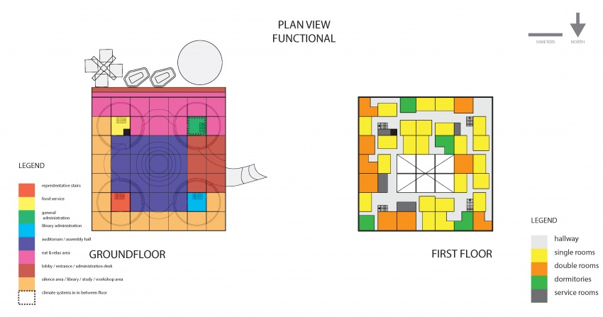
These plans show the program. On the bottom floor the sides around the entrances are the lobby and entrance area. They have functions like an administration office and a registration desk in one of the stems. In the centre, lies the auditorium. The edges of the bottom floor are divided into two: a silent part and a non-silent part. The latter consists of the dining area and the lobby. The dining area is situated on the south, next to the dock. Besides eating, people can relax and talk and sometimes take part in a workshop. On the other side, the northeast side, the place is characterized by a library and different study places. People can think and read.
On the second floor the studios are divided into three: single rooms, double rooms and dormitories. They are as much mixed up as possible.
What does the building look like?
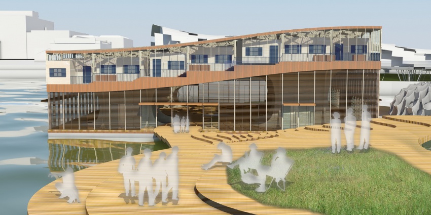
Elevation view from De Geleerde Netwerk, notice the urban routing of DGN flawlessly running into the Knowledge Centre.
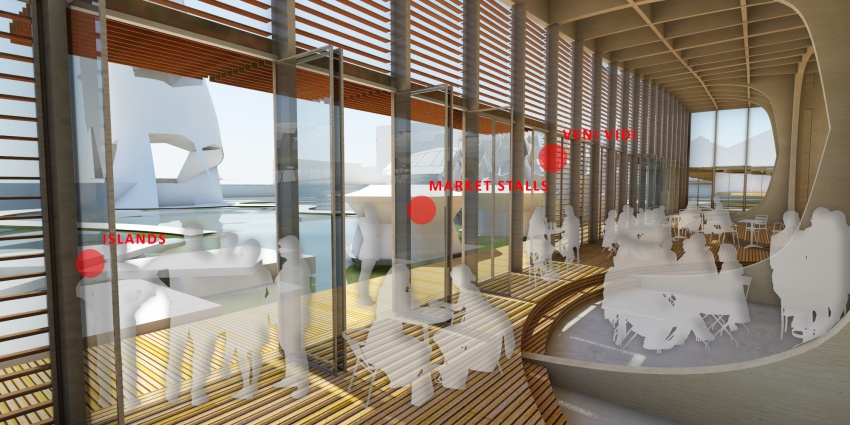
Interior view of the southwest facing dock / eating and relaxing area, looking towards the connection dock for Veni Vidi, Islands and the marketstalls of Reizende Drijvende Markt;
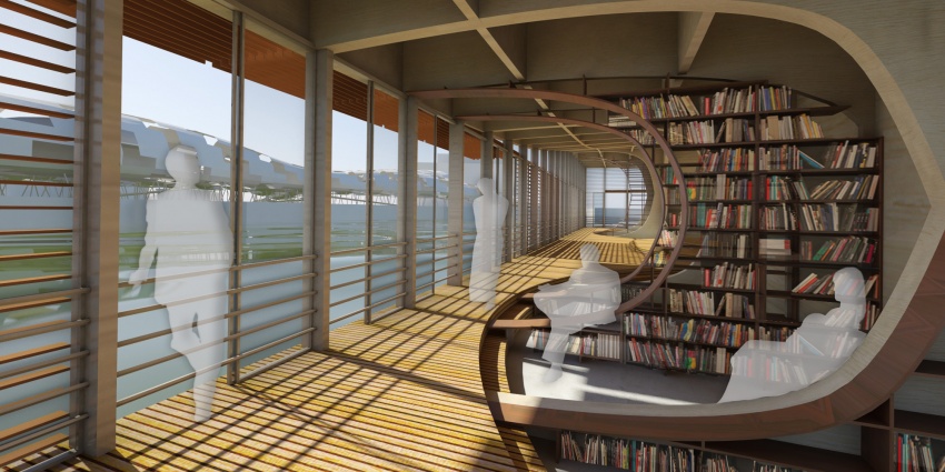
Interior view of the southeast facing library and study area, looking towards the Rejuvenative Sandwich;
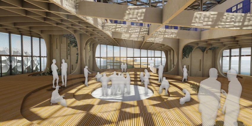
Interior view of the central auditorium area, towards the entrance and De Geleerde Netwerk. People meet, talk, discuss, debate, listen and lecture;
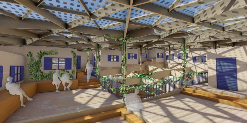
Interior view of the second floor from the southeast core looking towards the void area, notice the PV cells on the ETFE roof cushions;
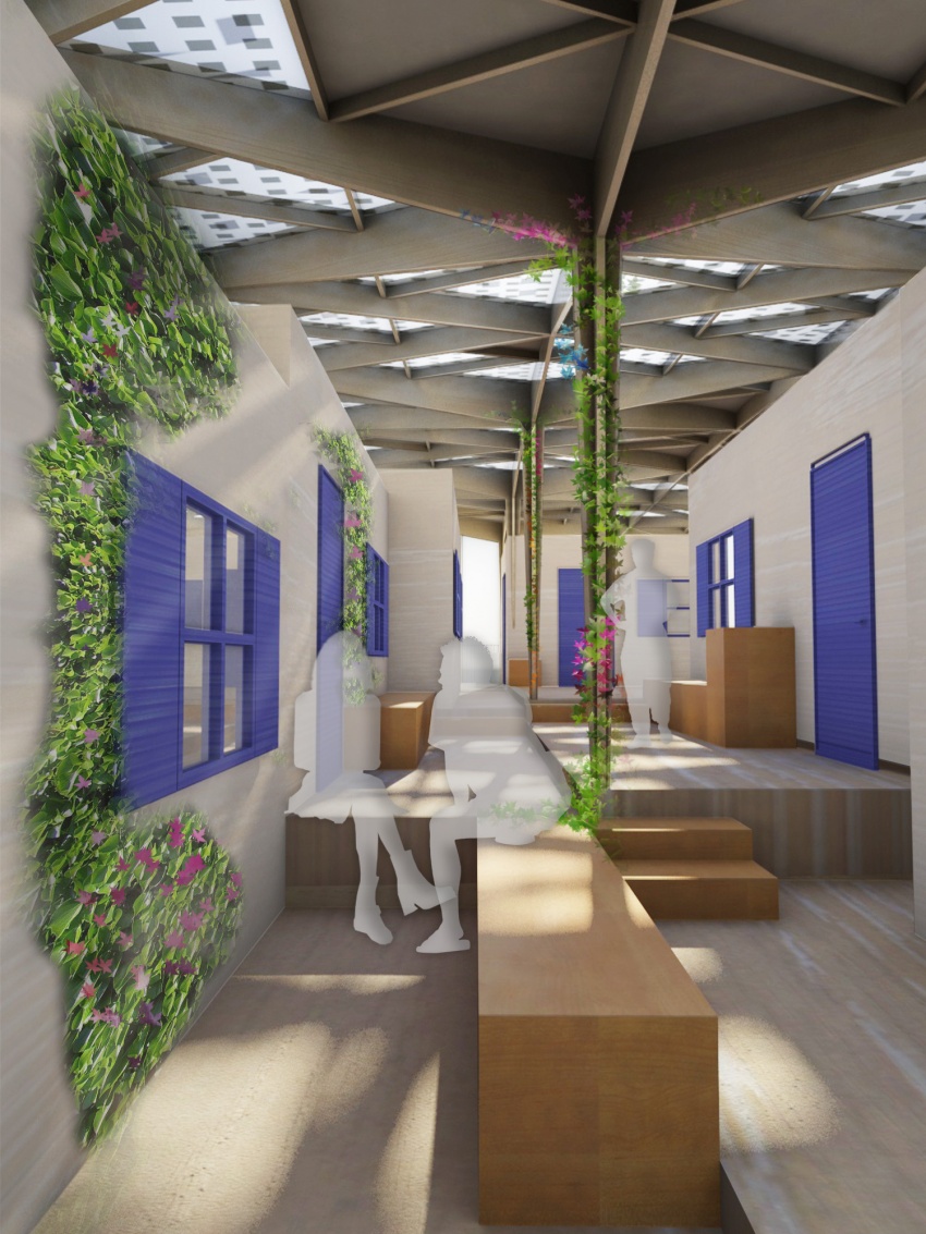
Interior view of a hallway between the studios on the second floor, looking towards the west, notice the closeable ETFE cushions when too much sun light or heat radiation is available;
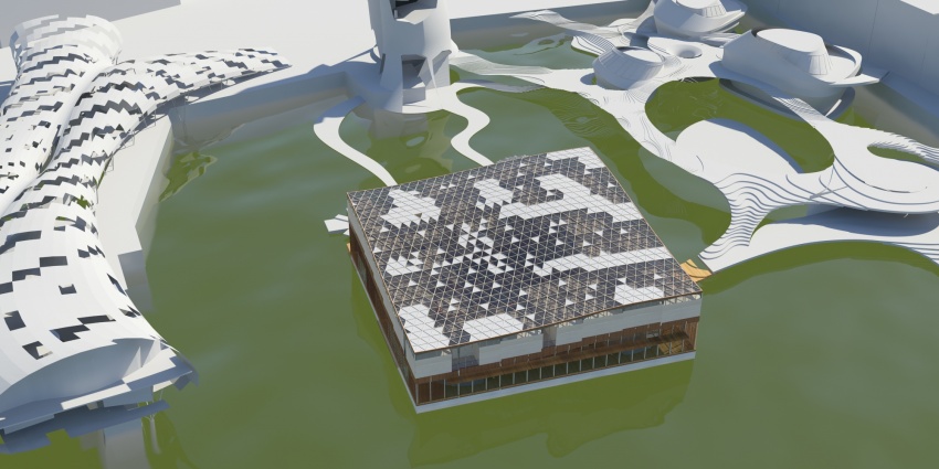
Bird's eye siteview: on the left the rejuvenative sandwich, on the right DGN and on the top Vfood restaurant.
COMPUTER AIDED DESIGN
The major advance of modeling with Grasshopper is the possibility to add changes. At the same time, this often leads to spending too much time on making some building parts unnecessary parametric. Because this was the first time for me working with Grasshopper, it was quite an interesting experience.
The input in my grasshopper definition consists in basics of:
- -a curved (inspired by the elevation of a Greek village) surface [SURFACE TOP] measuring 42mx42m (studio grid of 6mx6m combined with the demands on the volume (9000m3);
- -studio grid parameters of 6mx6m;
- -four points [POINTS CORE] on the xy plane within the boundaries of the surface representing the centres of the cores of the metropol parsol structure;
- -six different studios with platform [STUDIO GEOMETRY] and corresponding reference box [BOX REF];
The different outputs are each explained in the following paragraphs:
Creating the main structure
At first the [SURFACE TOP] is projected on the xz plane creating the [SURFACE BOTTOM]. Secondly, both surfaces are divided into the 6mx6m studio grid. From the division output [DIVISION OUTPUT] the grid lines [CURVES TOP X] AND [Y] are created. Same is done for the [SURFACE BOTTOM] ([CURVES BOTTOM X] and [Y]).
To create the characteristic curves of the structure in sevilla all curves are divided into 500 points [POINTS CURVES BOTTOM] [POINTS CURVES TOP] with fixed distances in resp. X and Y direction. The distance between these points and [POINTS CORE] are measured and tested if they are within a certain range (5 to 15 meters). Within this range, the curved shapes of the structure will be formed. At distance five and smaller, the z coordinate of the point will be replaced by half of the value of the z coordinate of the corresponding [POINTS CURVES TOP]. By repeating this z replacement for the [POINTS CURVES TOP] in the other direction, both points are joined. At distance 15 and further, the points will not be moved in z-direction. Between distance 15 and 5, the movement will increase exponentially and thus creating nice curves. These curves are baked into Rhino and served as the basis of the structure.
Creating the planes and studios
Using the [DIVISION OUTPUT] horizontal target boxes [BOX TARGET] are created on the [SURFACE TOP]. A list of a random collection of [STUDIO GEOMETRY] with the same length as the amount of [BOX TARGET] is created. This list is projected into the [BOX TARGET]. This geometry is baked in Rhino where the public area is optimized and the void is created.
Creating the roof structure
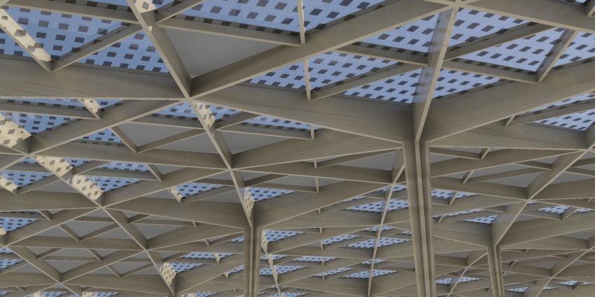
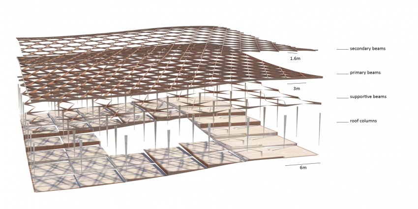
These two files show a closer view of the roof structure. They are also featured in the performance section. The first one is a detailed view, the second one an exploded view, also for support of the text under it explaining the script.
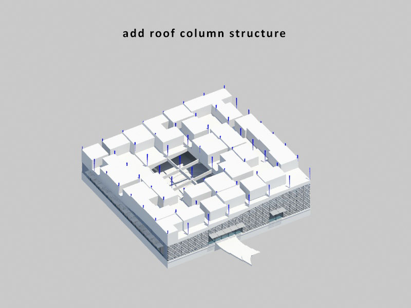
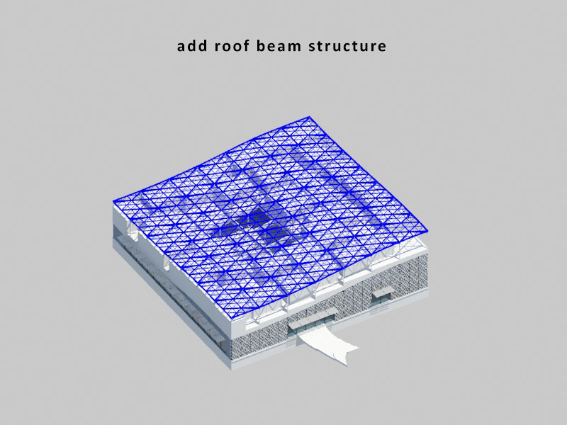
By moving the [SURFACE TOP] upwards a plane is created for the roof. By dividing this surface into a grid of points [POINTS ROOF] and shifting and culling the list in different ways, one can create the grid of lines [LINES ROOF] that results into the roof grid. By extruding these, the beams of the roof structure are created. By another selection of [POINTS ROOF] some points are picked, corresponding to the points from [DIVISION OUTPUT]. These points [POINTS ROOFCOLUMNS] correspond to the grid of the roof ([DIVISION OUTPUT] above). Between these points lines are drawn as the core of the roof columns [LINES ROOFCOLUMNS]. Next the [POINTS ROOF] are selected on their distance from [POINTS ROOFCOLUMNS], thus the supportive beams and columns can be created. The [POINTS ROOFCOLUMNS] are slightly shifted over the corresponding [LINES ROOFCOLUMNS] towards their base. A line is created between these points and the [POINTS ROOF] adjacent to each [POINTS ROOFCOLUMNS]. The result is lofted with the [LINES ROOF] and thus the supportive beams are created. The shape of the columns is created in the same way, but then by slightly shifting the [POINTS ROOFCOLUMNS] towards the adjacent [POINTS ROOF] over the [LINES ROOF]. The output is baked and given thickness in Rhino.
Besides the above, also the downstairs shading system is created parametrically, mainly by the use of curve divisions in x or y direction. Unfortunately due to a lack of time and other approaching deadlines really elaborating on the Grasshopper definition was not possible. Hopefully the story of the logics behind the model is clear.
