project23:Styling
Formal Reference: Origami as Deployable Structure
Origami Tessellations
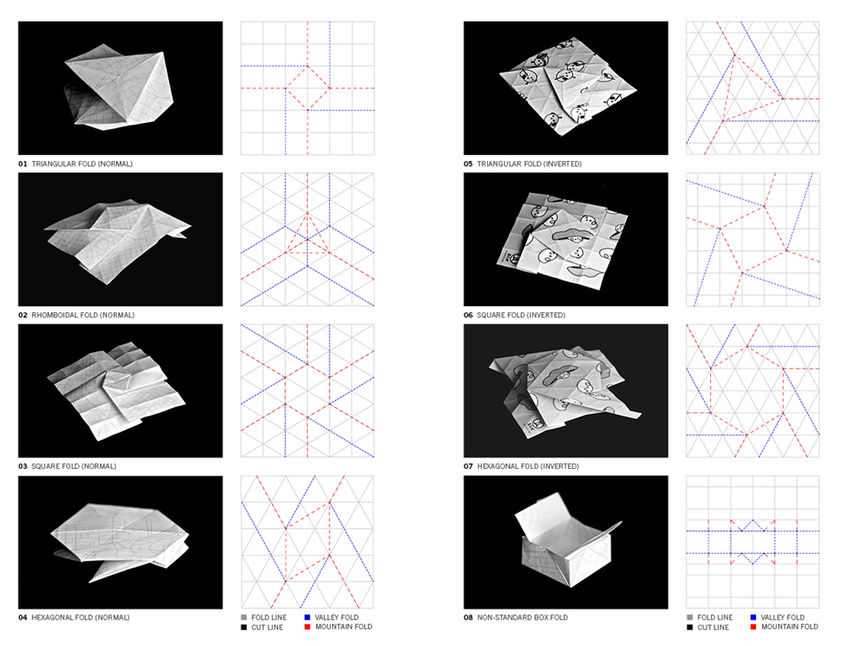
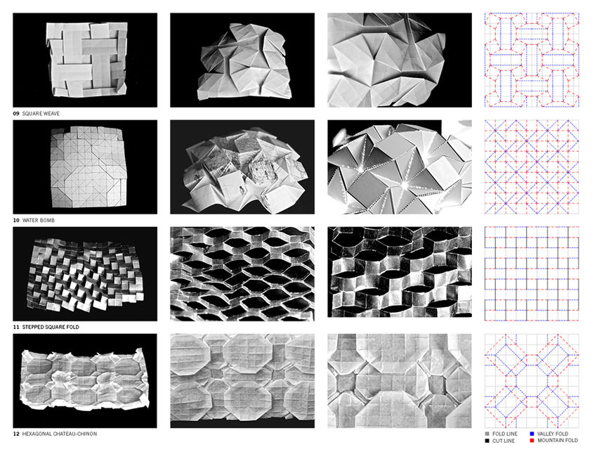
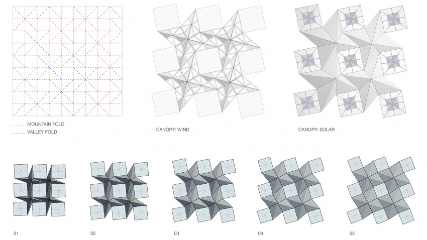
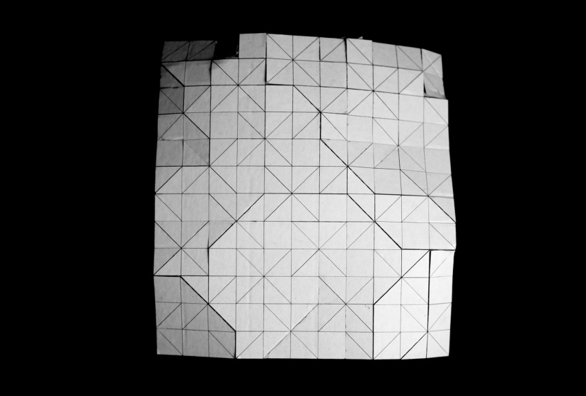
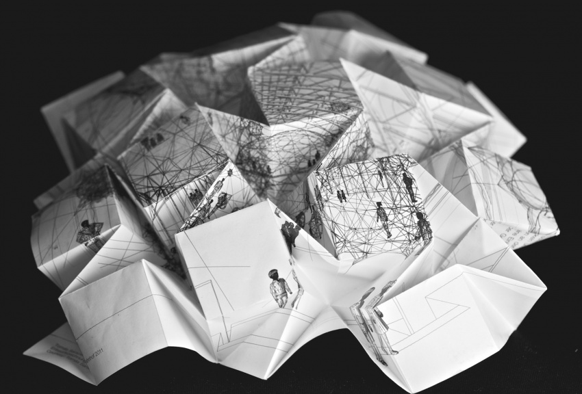
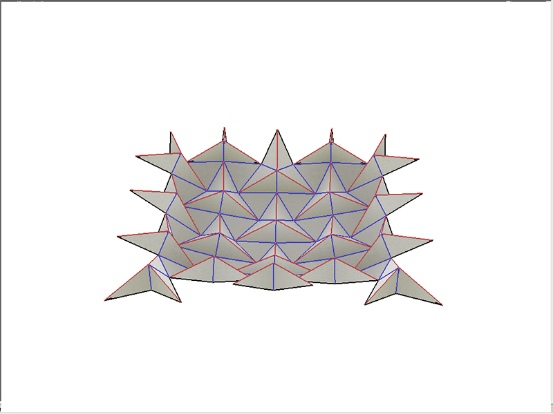
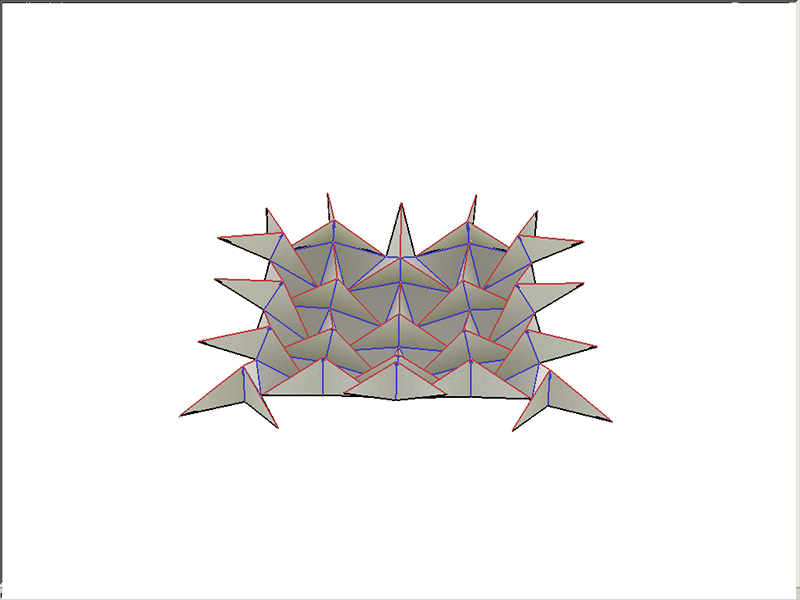
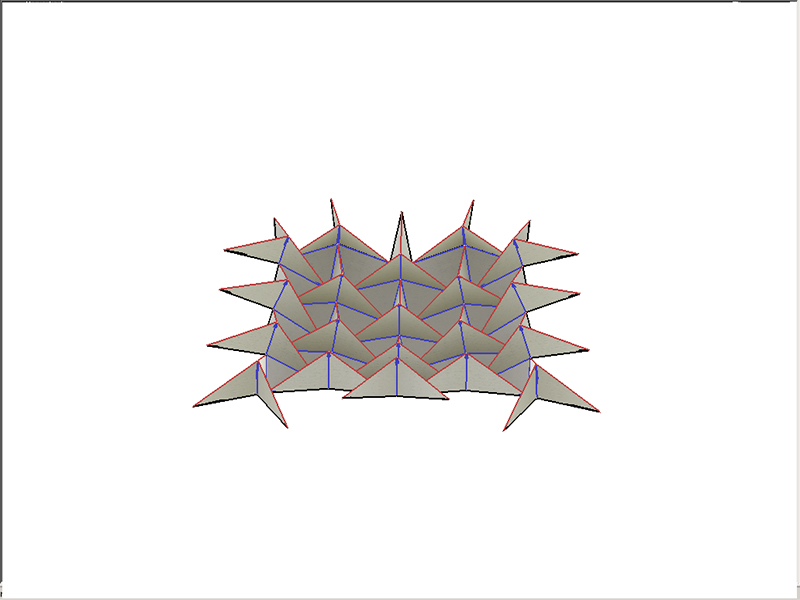
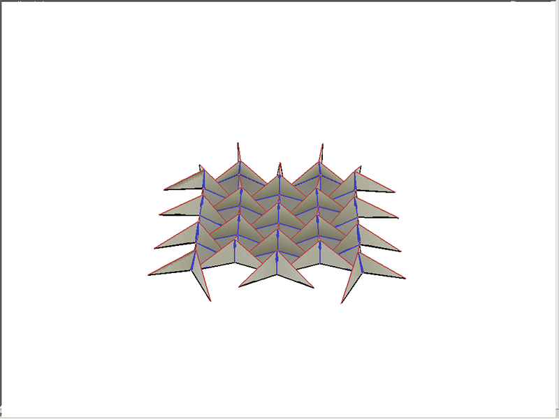
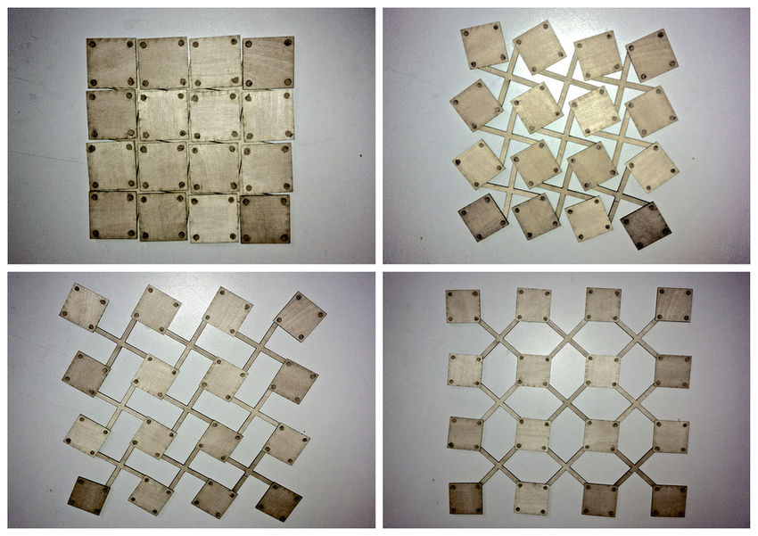
Origami tessellations, as defined in Eric Gjerde’s “Origami Tessellations,” consist of repeating patterns of specific shapes. The “Water Bomb” origami tessellation pattern stems from the basic origami square twist, which features four perpendicular pleats. Here, the Water Bomb pattern is used as the basis for the styling of an optional canopy for the Deployable Bridge. The canopy can follow the deployment of the base nearly through its full rotation, and its components are contained in the storage space of the base platforms (◘).
The Question of Rigidity
The position and angle of rotation of the canopy panels are based on the crease pattern of the Water Bomb pattern. As explained in Tomohiro Tachi’s “Rigid-Foldable Thick Origami,” hinges would be located along the normally creased edges for continuous transformation of the canopy. In their current arrangement, the panels would behave differently from the typical Water Bomb tessellation by experiencing deformation of its members and remaining planar throughout their deployment. In order for the canopy to remain planar and deploy in parallel with the bridge base, some vertices of the canopy would require elastic members. If the canopy was designed as a structure completely composed of rigid panels which parallels the kinetic behavior of rigid origami, the canopy would not remain planar throughout its deployment.
Synchronized Deployment
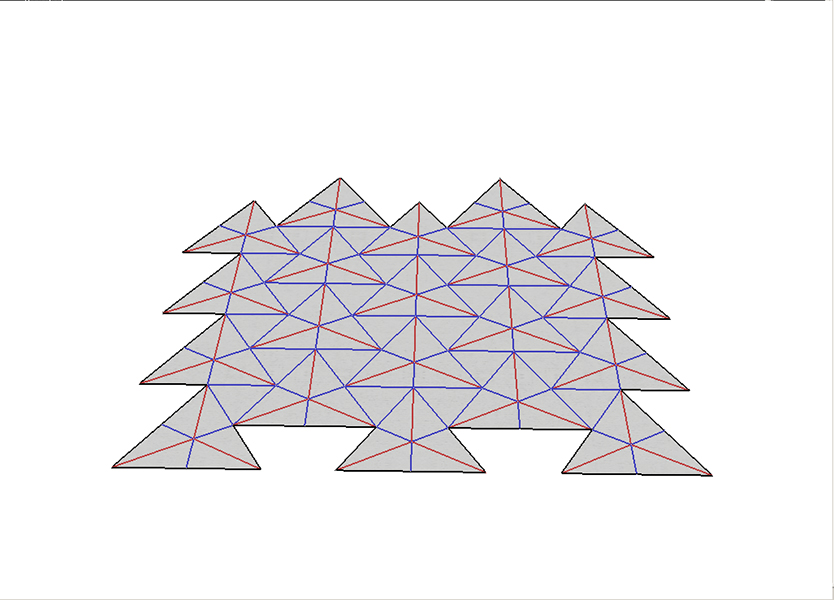
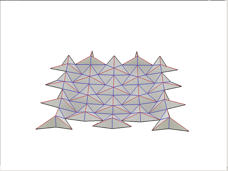
Synchronized deployment of base and optional canopy enables shelter from sun and rain throughout the transformations of the Deployable Bridge. The canopy is pliant in its three-dimensional transformation, effectively mirroring the flexible motion of its base. Tomohiro Tachi’s Rigid Origami Simulator software was used to simulate the angular and directional movement of the preliminary geometry for the canopy.
The Grasshopper plugin for Rhinoceros was used to determine the alignment of the Deployable Bridge base with the origami-inspired canopy. One preliminary difference between the behavior of the deployment of canopy and base is rotation; while the base platforms (◘) deploy, they rotate substantially while moving two-dimensionally, the canopy transforms in three dimensions and does not necessarily rotate in relation to its center as it deploys. To calculate a more seamless movement for the canopy, Daniel Piker’s Kangaroo plugin for Grasshopper can help determine the optimal component dimensions and angles of deployment.
Canopy Catalogue
The optional canopy would ideally include a catalogue of interchangeable panel options. These options might include a perforated surface to reduce wind load and a version equipped with solar panels to collect energy. Upon further exploration, the solar option could be greatly expanded to comprise an entire floating solar farm. The angle of the surfaces of the canopy could be adjusted for optimal sun exposure, and energy could be transferred from platform-to-platform into the smart units, which could serve as floating batteries. Optimally, this mechanism could extract excess energy generated by certain projects on-site and distribute this energy to projects in need.
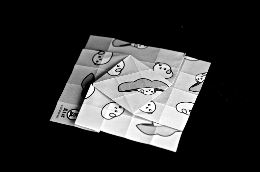
The Square Twist
Here is the square twist, which features four perpendicular pleats. The square twist forms the basis of many origami tessellations, including the “Water Bomb” pattern. This pattern provides a framework for the optional canopy for the Deployable Bridge.
Rigid Origami: Early Simulations
Tomohiro Tachi’s Rigid Origami Simulator software was used to simulate these early explorations for the canopy geometry. Different topologies, dimensions, and angles were tested to optimize the canopy in its three-dimensional transformation. In order to create a pliant canopy which effectively mirrors the flexible motion of its base, rotational and translational motion were measured for synchronization.
Preliminary Base Prototype
Early Sketches: Base Platforms
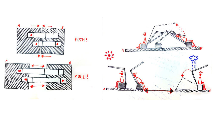
PUSH: When a platform-pair is pushed together, connective bands bend to form seating, shading, or shelter from rain.
PULL: When the platform-pair is pulled apart, the bands are flattened to create a connective bridge, or alternatively broken apart for further configurations.
Early Sketches: Platform Connections
LEFT: Puzzle Piece Connections. Users can configure platforms according to their distinct needs.
RIGHT: Different Platform, Different Funtion: (1) Swim. (2) Farm. (3) Relax (2 benches). (4) Relax (3 benches).
