project09:Styling
Last Version
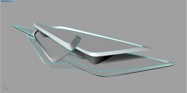
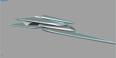
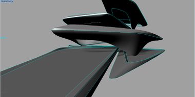
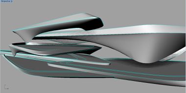
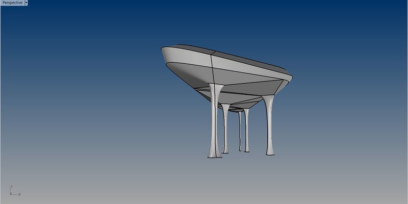
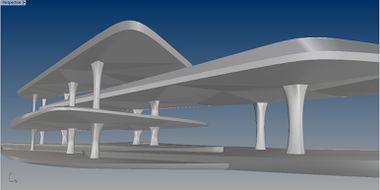
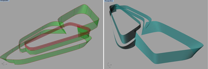
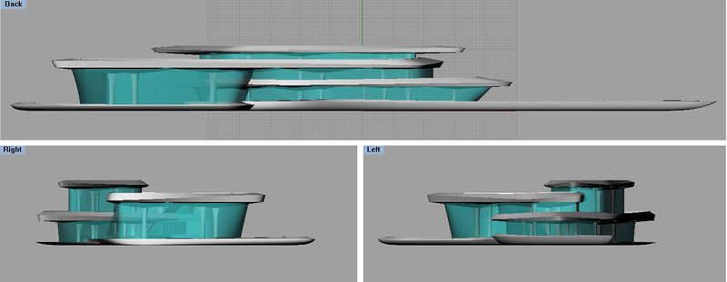
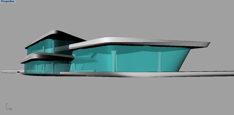
Our project starts with 3 platforms, which serve for Ferries, Private Boats, Mini Cargos and Sarah's boats respectively. The final figure forms from stacking more platforms with regard to specific funtions.
Problems of Last Version
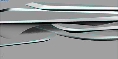
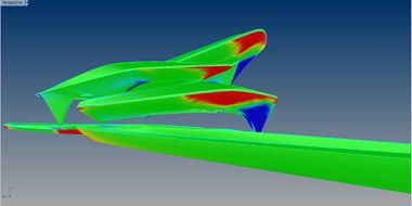
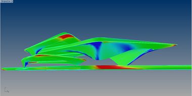
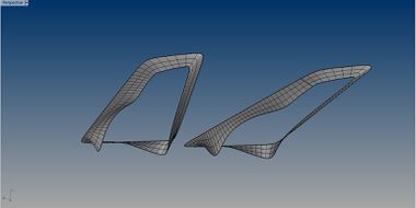
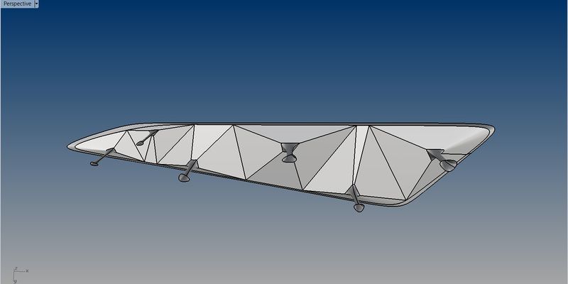
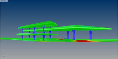
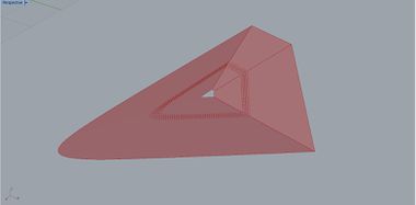
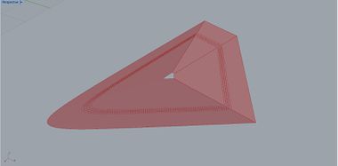
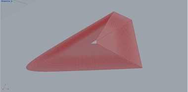
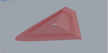
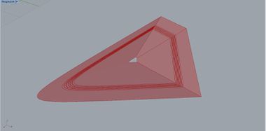
1. The 1st problem is surface curvature distribution, Which is not optimal for future fabrication, cause the better condition is that we can transfer more panels into flat ones.
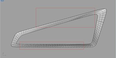
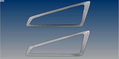
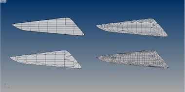
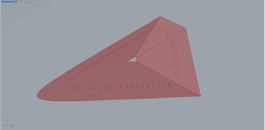
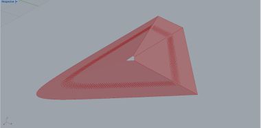
2. The 2nd problem is the isoframe cannot be used directly for panellization. What we do is rebuilding all surfaces in question based on referred contours, whilst not changing its appearance.
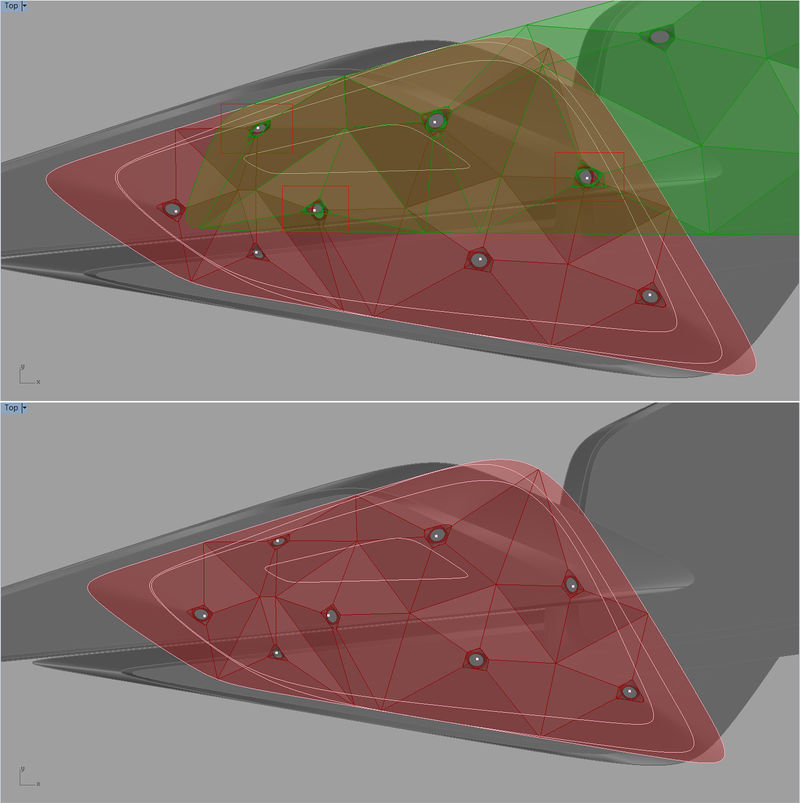
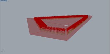
3. The last issue bothers us when we begin to design our structural system. In the last version, for each plate the basic logic is setting at least 3 supporting points, which go along with the contour. Unfortunately the stacking platforms are not simply repeated, all these supporting points cannot be organized under a feasible structure system without sacrificing much space or destroying the appearance. Then we explore different methods for optimization.
Exploration of Optimatization
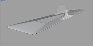
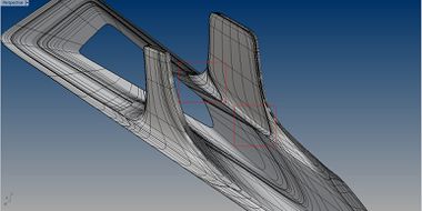
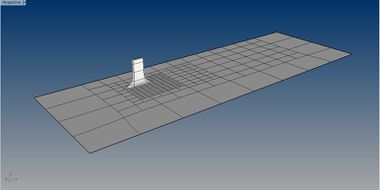
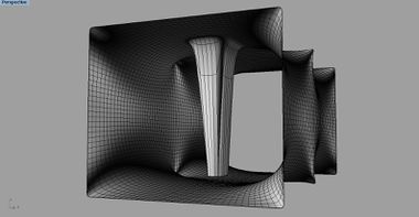
When the supporting points are free from the contours, we try to generate organic columns between two floors by T-Splines, the results turn out to be not smooth enough due to the specific isoframe, which is just the ideal situation when it's tidy grid.
Tensile-like structure could solve the problem brought about by unusual isoframe, at the beginning constraining the place of columns as well as the contour of the ceiling, then the structure is generatesd automatically by software like Evolute-Tools. But new trouble is what's the size of colums? and How to control it?
Current Solution
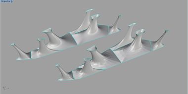
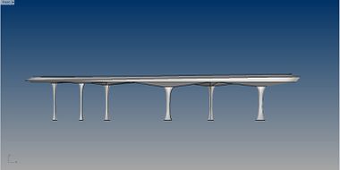
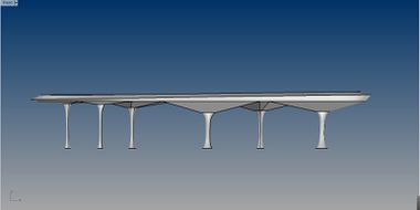
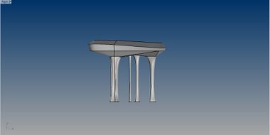
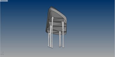
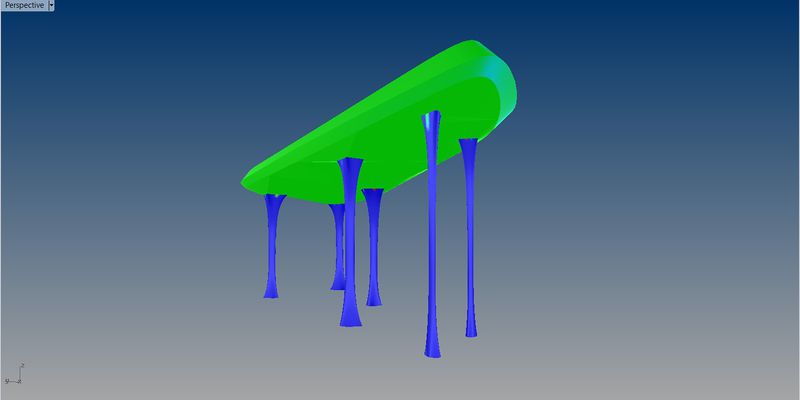
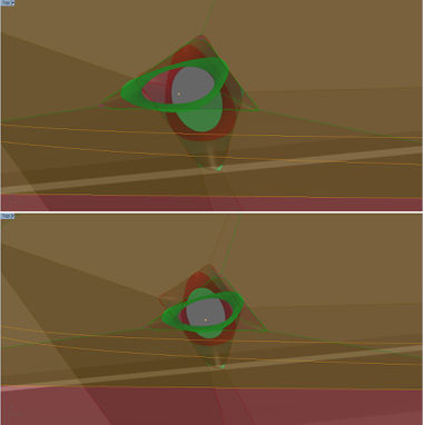
Finally we figure out a better approach which can be applied to every plate and the structure as an entirety of the building, integrating Voronoi with Mathematically Minimal Surface. We set a common scaling factor for each column, therefore the size depends on the area it is supporting. Voronoi makes the distribution for each column scientific, and the shape of columns structurally optimal. Besides that, the height of all Voronoi units are connected with the the size of them with respect to better structure.
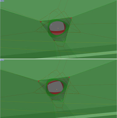
When we are applying this method to our whole project, some pratical issues appeared, such like the shape of the column, the size of respective columns enveloped by minimal-surfaced finish, the connection between columns ant different levels, and the relationship between columns and space around them.
Unit structure
Facade
Interior Lighting
