project13:Performance
(→Introduction) |
(→Roof structure) |
||
| (14 intermediate revisions by one user not shown) | |||
| Line 21: | Line 21: | ||
=Introduction= | =Introduction= | ||
| − | = | + | This section mainly covers the constructional side of the project. In the introduction part some general ideas are shown about the structural principles. In the second part some more detailed diagrams of the structure are shown and finally a detailed section of a part of the building. |
| + | |||
| + | =General structure= | ||
| + | |||
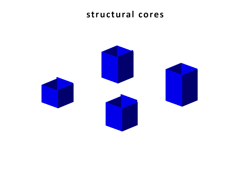
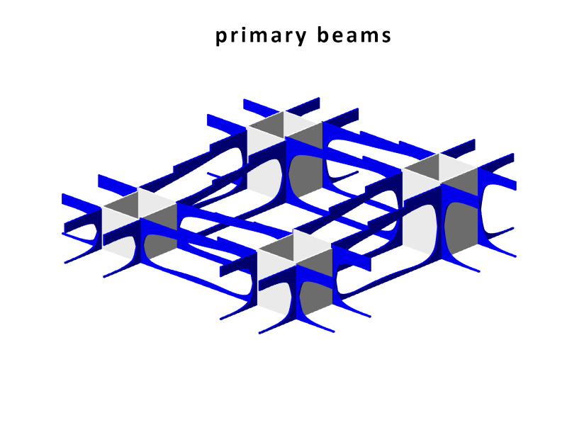
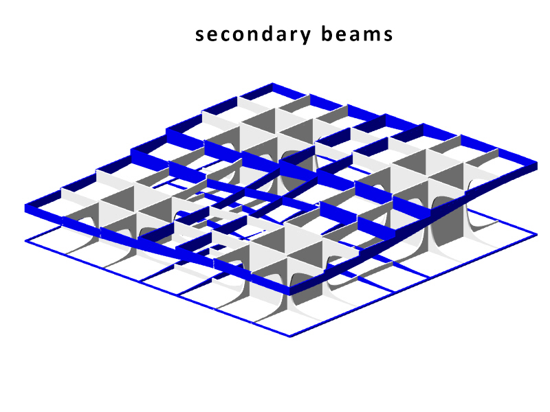
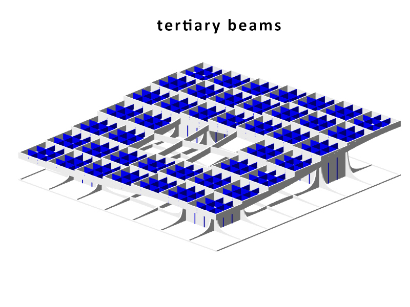
| + | The structure of the Metropol Parasol is quite interesting. Although the structure looks like a strict grid where every member has the same characteristics, this is not true. Some beams are larger than others and some beams are longer than other which are then divided at the intersections. The same is true for the Knowledge Centre. The structure is built up out of certain parts that are visible in the beneath following animation. As you can see the stems act as columns, and the beams are divided into primary (which direct forces towards the beams), secondary (which direct forces towards the primary beams) and tertiary beams (which direct forces towards the primary and secondary beams and take up the forces of the platforms). The columns, on their account, direct towards towards pontoon. The pontoon consists of an EPS foam core, split by a framework of reinforced concrete. A common, but recently developed, method in the Netherlands. The EPS not only acts as a floating member, but also as insulation of the bottom floor. The EPS pontoon is covered by a cassette concrete floor, which cassettes are 'created' by canals in the EPS blocks. A section of the pontoon is visible in the main section, at the bottom of this chapter. The reinforced concrete framework is striped. | ||
{{#slideshow: | {{#slideshow: | ||
| − | <div>[[ | + | <div>[[File:13_steigenga_performance_diagram01.jpg| 850px]]</div> |
| − | <div>[[ | + | <div>[[File:13_steigenga_performance_diagram02.jpg| 850px]]</div> |
| − | <div>[[ | + | <div>[[File:13_steigenga_performance_diagram03.jpg| 850px]]</div> |
| − | <div>[[ | + | <div>[[File:13_steigenga_performance_diagram04.jpg| 850px]]</div> |
| − | <div>[[ | + | <div>[[File:13_steigenga_performance_diagram05.jpg| 850px]]</div> |
|id=bar sequence=forward transition=fade refresh=3500 | |id=bar sequence=forward transition=fade refresh=3500 | ||
}} | }} | ||
| − | + | =Structure Diagrams= | |
| − | + | The Metropol Parasol consists of solid CNC milled beams. There are beams in the construction of up to 24 meters long. The connections are specially developed for the hot and humid climate in Spain. In fact at some parts, the main force distribution is carried by steel and steel knots, instead of the wood. In the Knowledge Centre, everything has to be light as possible, but the 'atmosphere' and character of the structure has to be strong. That is why the structure is created out of assembled timber beams. Generally: two beams at a certain vertical distance from each other to take up forces in their normal direction and two timber plates on either side of them to redirect the vertical forces. The two timber plates are created similarly to the structure in Seville, by CNC. The laminated beams are bend. The connection will be quite simple, because the interior climate is controlled, stretch and shrinkage will be a minimum. In the following three diagrams one can see the structure of the core, the primary, secondary and tertiary and the floor heated platforms. | |
| + | [[file:13_steigenga_performance_diagram_core.jpg|850px]] | ||
| − | |||
| − | The | + | As you can see in the next diagram. The actual primary beam consists of the two bottom, secondary and platform connections. |
| + | |||
| + | [[file:13_steigenga_performance_diagram_primbream.jpg|850px]] | ||
| + | |||
| + | |||
| + | Note for the next diagram: the red lines indicate that the plates are cut through in the drawing, to show the inside of the beams. In reality the plates cover the complete sides. | ||
| + | |||
| + | [[file:13_steigenga_performance_diagram_secbream.jpg|850px]] | ||
| + | |||
| + | |||
| + | =Roof structure= | ||
| + | |||
| + | The images in this paragraph are also featured in the styling section, but apply as well to the performance section, that is why they are also shown here. A close-up view and an exploded view, showing all the elements. | ||
| + | |||
| + | |||
| + | [[File:13 steigenga roof.jpg|425px]] | ||
| + | [[File:13 steigenga roof structure.jpg|425px]] | ||
| + | |||
| + | =Section= | ||
| + | |||
| + | In the main drawing of this paragraph, one can see the section. The sections' place is indicated in the next image: | ||
| − | |||
| − | + | [[file:13_steigenga_sectiondiagram.jpg|425px]] | |
| − | |||
| − | In the | + | Everything what is covered above, is also visible in the section. Additionally notice the following: |
| + | * -Openable small windows at the top of the first and second floor for natural ventilation all year long; | ||
| + | * -Because the building has a huge glass surface, it acts as a greenhouse. In winter, this is very nice. In summer, not so much. That is why the complete bottom facade, and all of the glass facade at the top floor, can be opened up. Additionally the ETFE cushions can be darkened (see illustration), besides they harvest solar energy which can provide electricity for additional cooling and heating. To provide extra natural ventilation + cooling in summer, a complete cushion can be opened by raising it. | ||
| − | |||
| − | + | [[file:13_steigenga_performance_etfe.jpg|425px]] | |
| − | |||
| − | * - | + | * -Notice the top floor heating and the bottom floor heating in the concrete floor parts. The floor heating illustrates the line between up and down, public and more private areas. |
| − | + | * -Notice the shading system at the bottom floor is shiftable towards the ceiling. | |
| − | * - | + | * -Not visible in this section: in the top floor shading is provided by curtains and luxaflex. |
| − | * - | + | * -Please click on the image to enlarge it. |
| − | + | ||
| − | + | ||
| − | + | ||
| − | + | ||
| − | |||
| − | |||
| − | |||
| − | |||
| − | |||
| − | |||
| − | + | [[file:13_steigenga_performance_section.jpg|850px]] | |
| − | + | ||
| − | + | ||
| − | + | ||
| − | + | ||
| − | + | ||
Latest revision as of 16:02, 21 January 2013
Contents |
[edit] Introduction
This section mainly covers the constructional side of the project. In the introduction part some general ideas are shown about the structural principles. In the second part some more detailed diagrams of the structure are shown and finally a detailed section of a part of the building.
[edit] General structure
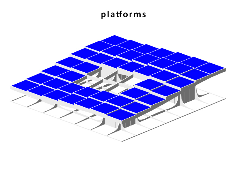
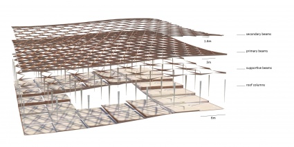
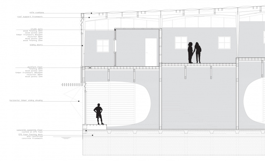
The structure of the Metropol Parasol is quite interesting. Although the structure looks like a strict grid where every member has the same characteristics, this is not true. Some beams are larger than others and some beams are longer than other which are then divided at the intersections. The same is true for the Knowledge Centre. The structure is built up out of certain parts that are visible in the beneath following animation. As you can see the stems act as columns, and the beams are divided into primary (which direct forces towards the beams), secondary (which direct forces towards the primary beams) and tertiary beams (which direct forces towards the primary and secondary beams and take up the forces of the platforms). The columns, on their account, direct towards towards pontoon. The pontoon consists of an EPS foam core, split by a framework of reinforced concrete. A common, but recently developed, method in the Netherlands. The EPS not only acts as a floating member, but also as insulation of the bottom floor. The EPS pontoon is covered by a cassette concrete floor, which cassettes are 'created' by canals in the EPS blocks. A section of the pontoon is visible in the main section, at the bottom of this chapter. The reinforced concrete framework is striped.
[edit] Structure Diagrams
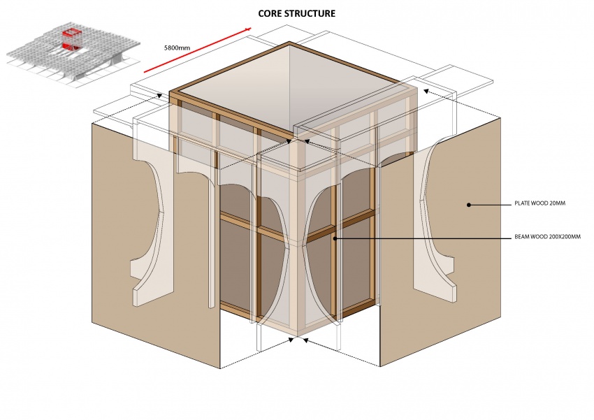
The Metropol Parasol consists of solid CNC milled beams. There are beams in the construction of up to 24 meters long. The connections are specially developed for the hot and humid climate in Spain. In fact at some parts, the main force distribution is carried by steel and steel knots, instead of the wood. In the Knowledge Centre, everything has to be light as possible, but the 'atmosphere' and character of the structure has to be strong. That is why the structure is created out of assembled timber beams. Generally: two beams at a certain vertical distance from each other to take up forces in their normal direction and two timber plates on either side of them to redirect the vertical forces. The two timber plates are created similarly to the structure in Seville, by CNC. The laminated beams are bend. The connection will be quite simple, because the interior climate is controlled, stretch and shrinkage will be a minimum. In the following three diagrams one can see the structure of the core, the primary, secondary and tertiary and the floor heated platforms.
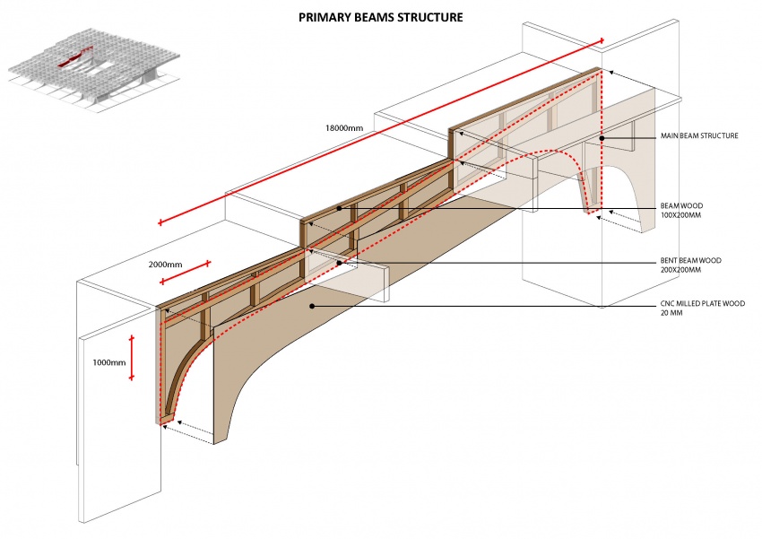
As you can see in the next diagram. The actual primary beam consists of the two bottom, secondary and platform connections.
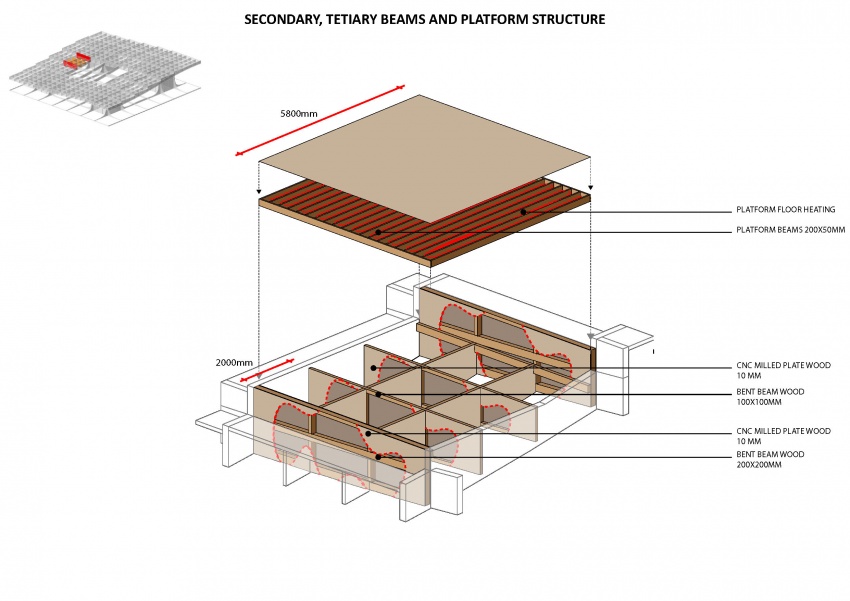
Note for the next diagram: the red lines indicate that the plates are cut through in the drawing, to show the inside of the beams. In reality the plates cover the complete sides.
[edit] Roof structure
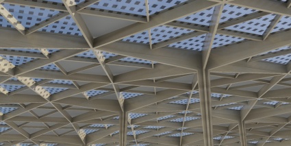
The images in this paragraph are also featured in the styling section, but apply as well to the performance section, that is why they are also shown here. A close-up view and an exploded view, showing all the elements.
[edit] Section
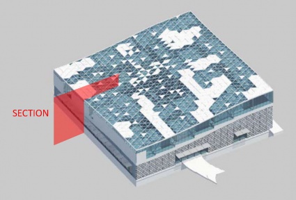
In the main drawing of this paragraph, one can see the section. The sections' place is indicated in the next image:
Everything what is covered above, is also visible in the section. Additionally notice the following:
- -Openable small windows at the top of the first and second floor for natural ventilation all year long;
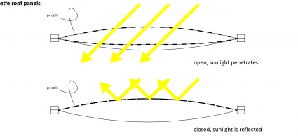
- -Because the building has a huge glass surface, it acts as a greenhouse. In winter, this is very nice. In summer, not so much. That is why the complete bottom facade, and all of the glass facade at the top floor, can be opened up. Additionally the ETFE cushions can be darkened (see illustration), besides they harvest solar energy which can provide electricity for additional cooling and heating. To provide extra natural ventilation + cooling in summer, a complete cushion can be opened by raising it.
- -Notice the top floor heating and the bottom floor heating in the concrete floor parts. The floor heating illustrates the line between up and down, public and more private areas.
- -Notice the shading system at the bottom floor is shiftable towards the ceiling.
- -Not visible in this section: in the top floor shading is provided by curtains and luxaflex.
- -Please click on the image to enlarge it.
