project23:Performance
| Line 115: | Line 115: | ||
[[File:PROJECT23 explode axon.jpg|850px]] | [[File:PROJECT23 explode axon.jpg|850px]] | ||
</div> | </div> | ||
| − | + | KEY: | |
| − | + | ||
A. Interchangeable rigid canopy panels with solar panel option | A. Interchangeable rigid canopy panels with solar panel option | ||
Revision as of 13:40, 20 January 2013
Contents |
Self-Constructing Architecture
If automated, the Deployable Bridge can represent a type of architecture which effectively builds itself.
Two-Unit System: ◘ & ✚
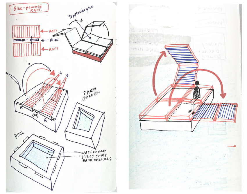
One distinct feature of the performance of the Deployable Bridge is its ability to act as simple linkage of two basic units (◘ and ✚). The units are connected and disconnect by a simple lightweight yet strong hinge around which both platforms (◘) and paths (✚) can rotate freely. This minimal model acts as a universal framework which supports a wide range of scenarios and reacts flexibly for disparate functions.
Base Geometry
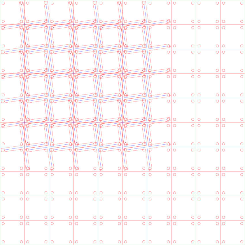
As a simple linkage of two basic units (SQUARE and CROSS), the base geometry was designed as a universal framework to support numerous configurations. A single platform unit (SQUARE) comprises only 16 m2. However, when single platform units (SQUARE) are combined with path units (CROSS) in a cluster or large field, a more buoyant, stable floating system emerges which can support greater weights and more complex functions.
Functional Constraints
The base was styled according to the constraints of several primary functions: bridge, chill-out spot, public platform, pontoon, water taxi, and storage container. When deployed, the base functions optimally as a bridging mechanism for collective transit; when closed, the base establishes a cohesive surface which maximizes usable surface area on water. Volumes which provide seating in the closed state open to provide railings in the deployed state. Smart units alone can act as water taxis for individual transportation.
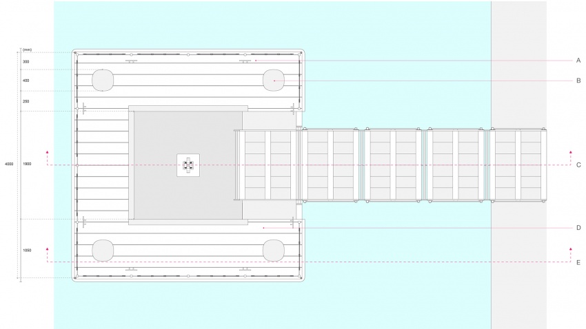
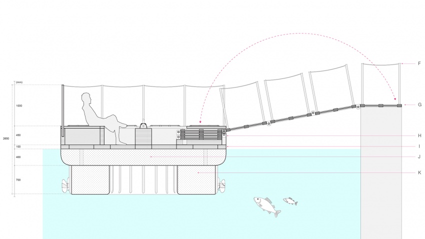
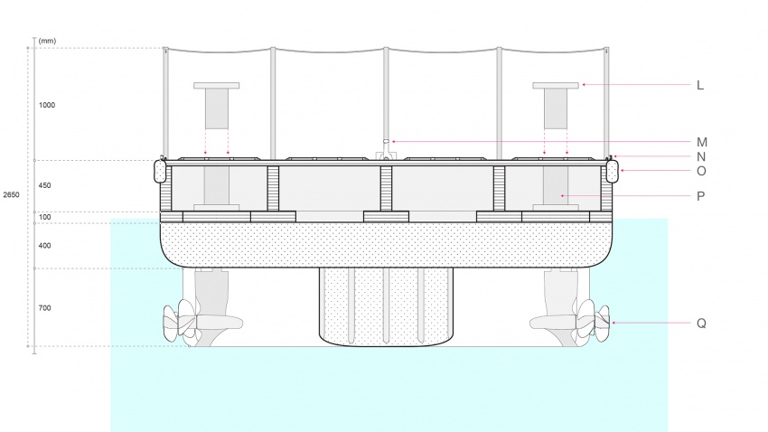
Smart Unit: Plan + Sections
KEY:
A. Galvanized Iron Cleat bolted into steel angle on frame
B. 400 mm diameter removable hinge connector, steel core with Polyethylene coating
C. Section Cut 01
D. 200 mm removable pressure-treated wood decking
E. Section Cut 02
F. 1 m removable aluminum safety railing
G. 4 m deployable gangway with 200 mm wood decking
H. Galvanized steel hinges with bolted connectors for deployable gangway
I. 100 mm pressure-treated wood frame, 1.5 m freeboard
J. High-density molecular weight Polyethylene HD-PE Lupolen
K. Polyethylene HD-PE Lupolen, buoyancy capacity of 376 kg/m2
L. 400 mm diameter removable hinge connector, steel core with Polyethylene coating
M. Manual engine controller, connected to GPS sensors
N. Red/Green navigation lights
O. Vinyl dock fender/bumper
P. 420 mm diameter Polyethylene tube (receives hinge connector)
Q. Volvo Penta DPS drive motor (directional thruster)
Logistics
As a system available for public use, the Deployable Bridge would ideally be automated and operated from a remote location. The operator could assign routes for specific functions and times by selecting from a list of pre-determined standard formations useful for common scenarios. These formations would comprise optimal spatial arrangements and degrees of deployment to suit select functions. Uncontrollable changes in the environment would trigger certain responses from the system. For example, an incoming ship would cause the deployed bridge formation to recede temporarily to allow the ship to pass. Smart units would be equipped with GPS to detect their position on-site and receive instruction signals from the operator.
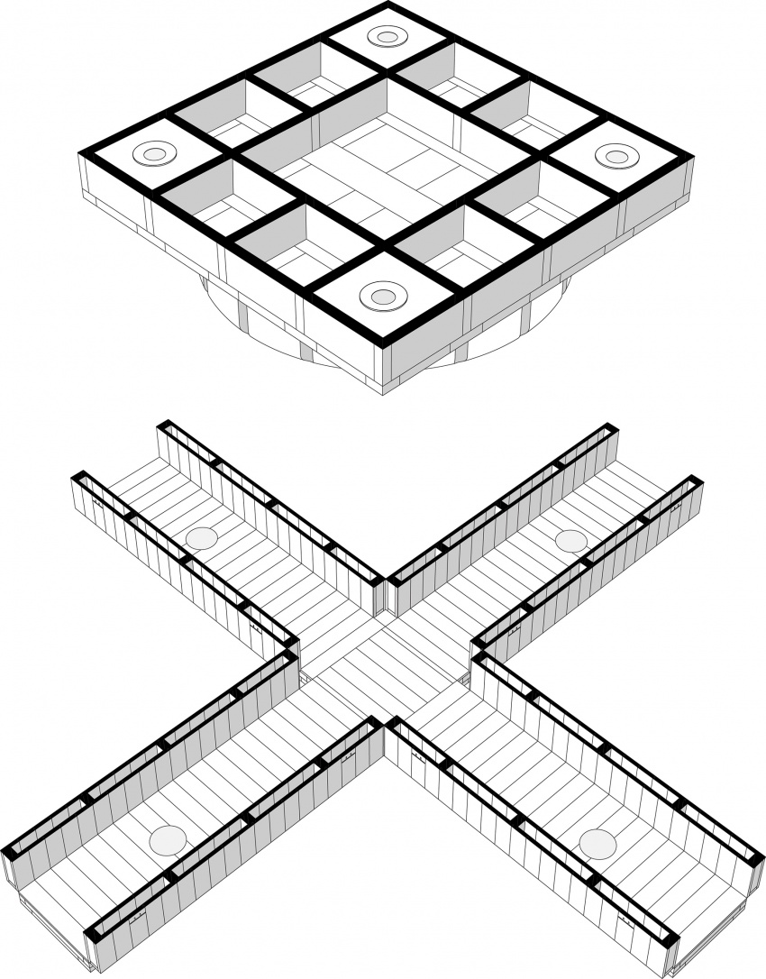
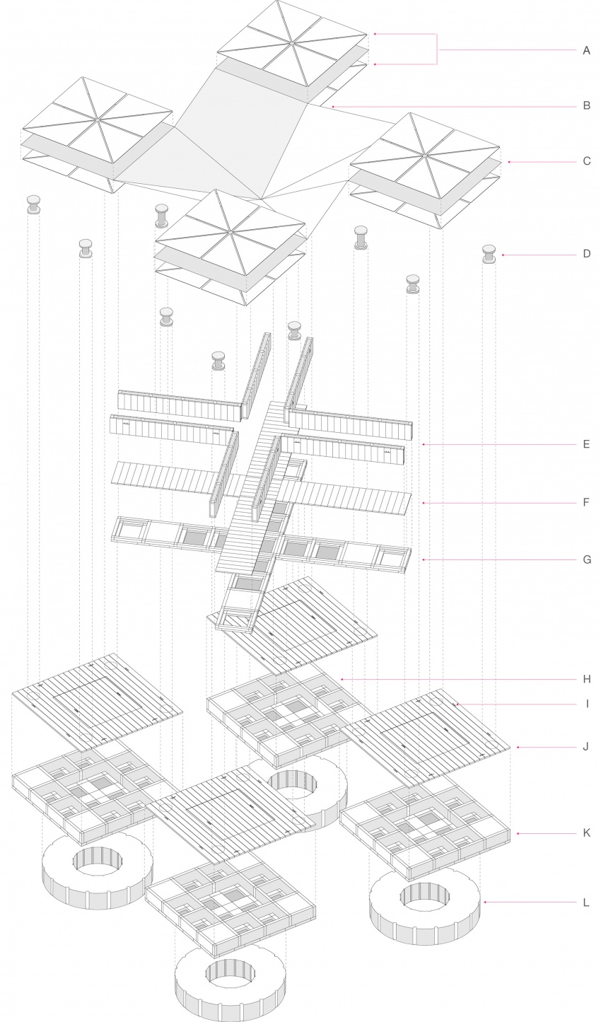
Smart Unit: Exploded Axonometric
KEY:
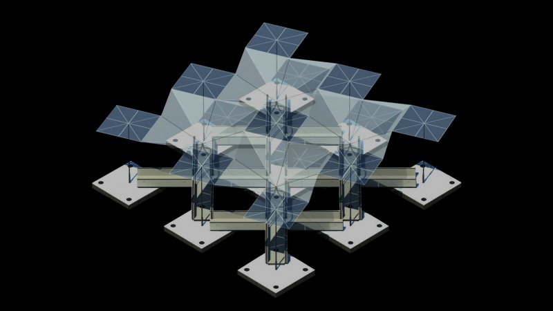
A. Interchangeable rigid canopy panels with solar panel option
B. Lightweight translucent canopy skin with elastic framework / pistons
C. Adjoining membrane sandwiched by rigid canopy panels
D. 400 mm diameter removable hinge connector, steel core with Polyethylene coating
E. 1 m tall wood frame railing, doubles as seating when not deployed
F. 200 mm removable pressure-treated wood decking for pathways
G. 250 mm tall 100 mm pressure-treated wood panel frame
H. 550 mm tall storage space containers for canopy members
I. Galvanized Iron Cleat bolted into steel angle on frame
J. 200 mm removable pressure-treated wood decking for platforms
K. 550 mm tall 100 mm pressure-treated wood panel frame
L. 700 mm tall Polyethylene HD-PE Lupolen, buoyancy capacity of 376 kg/m2
FORMATION 1: COMPACTED
0° / Solid Floor / Chill-Out Sport Modular components for Optional Covering are stored in each platform. Platforms are recessed below pathways to provide group seating. Optimal for lunch hours (students) and night life events (floating theater).
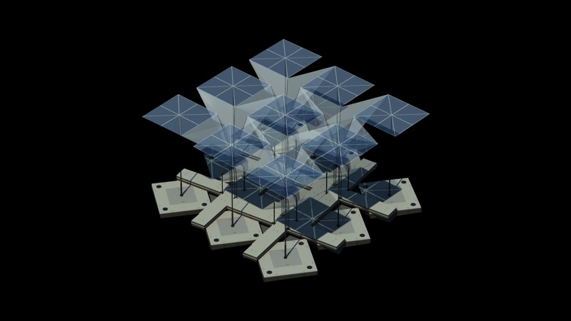
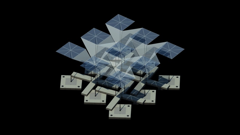
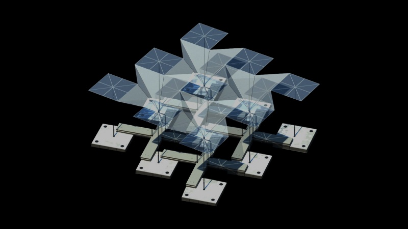
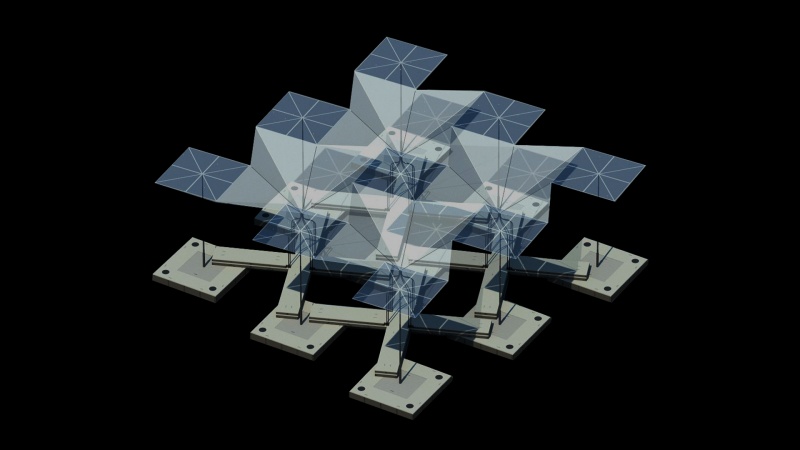
FORMATION 2: DEPLOYED
225° / Deployable Bridge / Greatest Reach This configuration is optimal as a bridging agent. Pathways should be flush and continuous in the final geometry. Platforms may be covered with a duplicate platform, thereby sandwiching the path geometry. Optional covering may include a deployable lightweight origami structure, formed by tracing the vertices and translation vectors of the rotation axes. Origami structure should include perforations to reduce wind load and may enable selection of different materials to guard against sun and rain.
VARIABLES
Variable 1: Position of rotation axis on platforms. Variable 2: Position of rotation axis on pathways. Variable 3: Width of platforms. Variable 4: Width of pathways.
CONFIGURATIONS
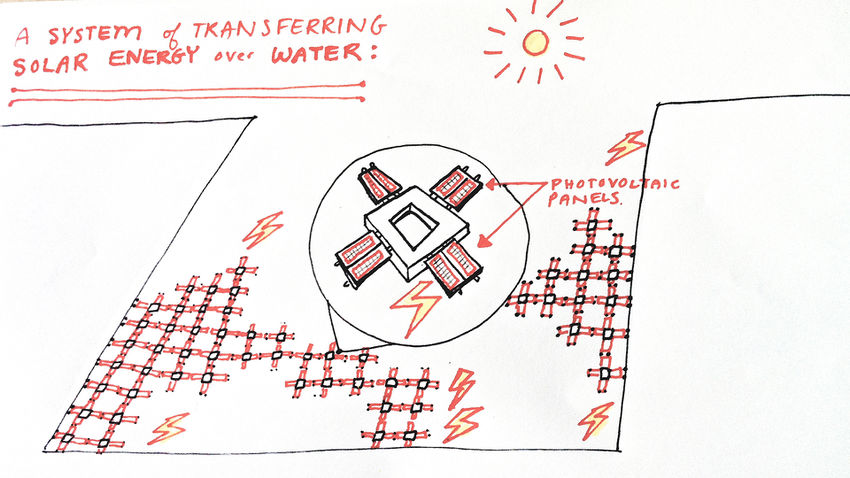
ISLANDS float freely and have the capacity to regroup and cluster around certain projects according to need. Since the islands cover a maximum surface area on the water, solar harvesting can be optimized and farm plants receive generous sun exposure.
== ACTIVITIES ==
ISLANDS aims to cover the purposes of recreation, relaxation, sustenance, and transit by offering different module types to support each activity. For example, an RDM student may choose an ISLAND to find a dry, sheltered place to chill during lunch break. Simultaneously, a second modular form may support a floating solar farm, with maximized surface area and flexible angle toward the sun. Then another may act as a pontoon for boat repair. Meanwhile, a fourth module may transport people to all the other projects on-site and any points along the shoreline.
CONNECTIONS
The most crucial goal of the form for ISLANDS is connectivity. The aim is to connect outsiders (at sea) with insiders (on land) -- essentially, to bridge marine life with shore life. This includes sailors, students, workers, and local residents -- as reflected in the CONNECTIONS section. Therefore, the form should be modular and nest-able (or tessellated somehow). The various organizations possible for the modules (as a group) should react to any number of parameters such as water surface area / human density, project density, climate, daytime/nighttime, sunlight/shading, etc. In addition, the modules themselves could react to such parameters -- specifically, with the bend angle of the connective bands/gangways.
